Microstrip interdigital filter requires use of grounding via-holes but the grounding via-holes will influence performance of interdigital filter. This will make the.
Interdigital Bandpass Filter Designer
Use a lathe to countersink the base and make a sharp level edge all around there is really no way to do this freehand.
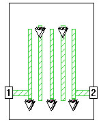
. To fit the filter in the box the width W1 of the three striplines plus the spacings S1 between them plus the side spacings ss must add up to the length of the box. Zverevs Handbook of Filter Synthesis is better for more modern filter design nomenclature and G. F 0 center frequency 51 GHz w bandwidth 340 MHz N number of poles 5 The filter will use a substrate with a dielectric constant of 98 and a thickness of 15 mils with 1 mil thick gold metallization.
147-152 Im assuming that youre capable of designing a top C coupled bandpass filter if not then youll have to work out how to do that first. Select any dielectric substrates such as PCB or Alumina and calculate the precise layout dimensions. The traditional design method does not consider grounding via-holes effect in the initial design process which will lead to some uncertainties of the grounding via-holes such as the number the size and the position.
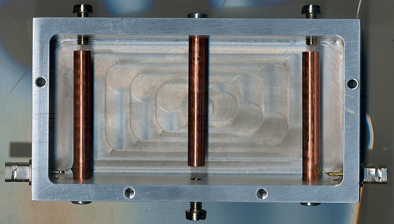
2Interdigital bandpass filter Structure. The filter are more realizable than the side filters. Microstrip Filter Design Tool Design distributed-element microstrip filters with low-pass or band-pass response and stubs stepped impedance or interdigital topology.
Denig Using microwave CAD programs to analyze microstrip interdigital filters Microwave Journal March 1989 pp. Hello everyone i m trying to design the 5th order interdigital microstrip bandpass filter in ADSi dont know how to calculate the dimensional values of resonator and i dont know the exact components for designing the filteri have used the dimensional values calculated for parallel coupled filter using line calculatorbut i didnt get the resultsplease if anyone knows. Port by the interdigital capacitor.
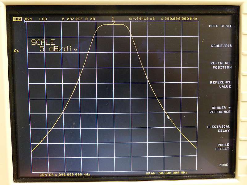
Conductor and substrate losses are not yet modeled. Bandpass ripple 0100 DB Center frequency 1420400MHZ Cutoff frequency 1417400 and 1423400 MHZ Ripple BW 6000 MHZ 3 DB BW 8334 MHZ Fractional BW 4224 MHZ Filter Q 170435 Est QU 1310986 Loss Based on this QU 2516 DB Delay at band center 85163 NS Freq DB loss. Figure 1 shows a type of interdigital bandpass filter commonly used for microstrip design.
3 converted into a form for Ansoft Designer SV simulation. Data Courtesy of Wentzel Erlinger. Look up Denigs paper on interdigital filters and use that with RFSim99 C.
Filter Design Example In this example the following bandpass interdigital filter is specified. The design is a first approximation and. Using an idea from crystal filter technology this circuit is used to develop the exact value of the interdigital capacitor required.
Design Notes 4400 MHz MICROSTRIP INTERDIGITAL FILTER This project shows a Printed Interdigital Microstrip Filter designed on a 25 mil Alumina substrate using Wentzel and Erlingers IDC Filter Synthesis program analysed in our 25D planar electromagnetic tool EMSight. Design data for 3 section interdigital bandpass filter. Microstrip Filter Design Tool is a web-based application for distributed-element microstrip filter synthesis.
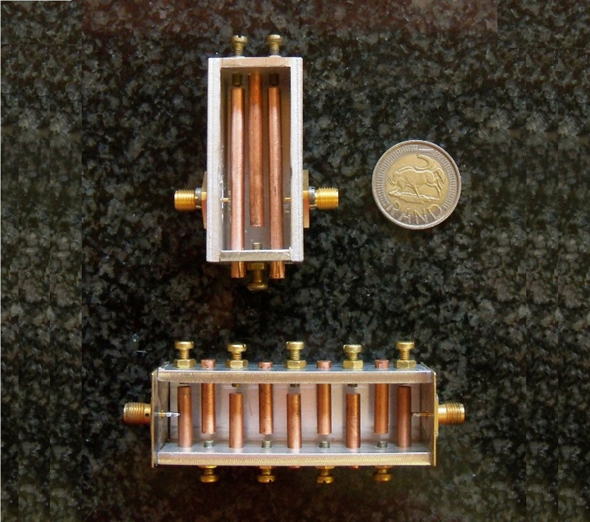
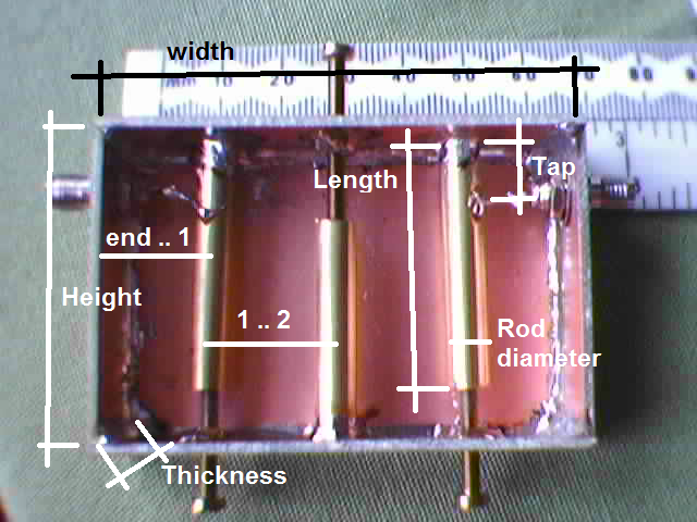
While th er is no problem with this theoretically in practice it is often simpler to usc round rods of equal d iamete n place of ec angular ones of various sizes. This tool is still in beta so use it with caution. The traditional design of interdigitated filters de scribed by Mauhaei Young and Jones calls for both the spacing and sizes of the rectangular resonantele ments to be variables.
Waveguide Dimensions for Interdigital Filters Frequency Waveguide Wide Dimension λ4 MHz WR-340 34 868 WR-284 284 1039 WR-229 229 1289 WR-187 1872 1577 WR-159 159 1857 WR-137 1372 2152 WR-112 112 2636 WR-90 090 3280 WR-75 075 3937 WR-62 0622 4747 Fig 1Interdigital filter cross-sectionWR-50 051 5789 sketch. -coupled There are also several implementations in addition to the microstrip medium including stripline coplanar waveguide and slotline. Matthei Young and Jones is the seminal work and was the starting point for many.
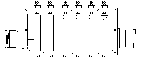
Box length 3 W1 2 S1 2 ss Click Backto return to the Specificationsscreen. Drill and tap a deep hole into the base of each element and assemble the filter using strong steel screws to pull each element tightly into the supporting bar youre actually hoping to make a cold weld. It is feature rich user-friendly and available for free from any desktop or mobile device.
The opposite phase signal supplied by the lower coil is fed via a second capacitor to the output port. Design digital FIR filters online with TFilter Calculate the resonant frequency of L-C circuits Single layer coil inductance calculator Design an Interdigital Bandpass Filter Circuit Sage A site with many filter design tools L Matching Network Calculator Impedance Converter using L C Microstrip Line Calculator Patch Antenna Calculator.
Interdigital Bandpass Filter Designer
Interdigital Bandpass Filter Designer
Interdigital Bandpass Filter Designer
Microstrip Interdigital Bandpass Filter Sonnet Software
Microstrip Interdigital Bandpass Filter Sonnet Software
Interdigital Filter

Interdigital Bandpass Filter Designer
Online Combline Bandpass Filter Designer
0 comments
Post a Comment